IQ Modulation
Spin qubit resonant frequencies are typically 2 to 20 GHz. This is much higher than the bandwidth of the AWGs. In experiments microwave (MW) sources are used to manipulate the qubits. The microwave signals must be amplitude and phase modulated for full qubit control. A common solution for this modulation of MW signals is in-phase and quadrature (IQ) modulation. The in-phase and quadrature MW sinusoids are mixed with an IQ modulation pair from the AWG. See In-phase and quadrature components.

IQ mixing with carrier frequency \(f_c\)
The output of this mixer is:
\(y(t) = I(t) cos(\omega_c t) - Q(t) sin(\omega_c t)\)
IQ modulation can be used to create a single frequency output signal which is higher of lower in frequency than the MW source. For this the IQ modulation signals should be sinusoids with a 90 degrees shift.
\(I(t) = A(t) cos(\omega_m t + \phi(t))\)
\(Q(t) = A(t) sin(\omega_m t + \phi(t))\)
\(y(t) = A(t) [cos(\omega_m t + \phi(t)) cos(\omega_c t) - sin(\omega_m t + \phi(t)) sin(\omega_c t)]\)
\(y(t) = A(t) cos((\omega_c + \omega_m) t + \phi(t))\)
IQ modulation allows frequency multiplexing, because it is a linear operation. The I and Q components can contain multiple frequencies which will all be shifted with \(f_c\). IQ modulation can also be used for fast chirps (frequency sweeps), because phase and frequency of the I and Q components can be swiftly changed by the AWG.
IQ modulation in pulse_lib
Users of pulse_lib don’t have to care about the calculation of I and Q outputs. They can specify the desired MW pulses after IQ modulation and pulse_lib calculates the I and Q output signals for the AWG.
The user has to specify the I and Q output channels of the AWG as an IQ pair and pass the frequency of the vector signal generator, the LO frequency. For coherent qubit control every qubit needs a channel with the resonant frequency of the qubit.
- Example:
pl.define_channel('I1','AWG1', 3)
pl.define_channel('Q1','AWG1', 4)

# define IQ output pair
IQ_pair_1 = IQ_channel_constructor(pl)
IQ_pair_1.add_IQ_chan("I1", "I")
IQ_pair_1.add_IQ_chan("Q1", "Q")
# frequency of the MW source
IQ_pair_1.set_LO(2.40e9)

# add 1 qubit: q1
IQ_pair_1.add_virtual_IQ_channel("q1", 2.415e6)
IQ modulation errors
Idealy the IQ mixer creates single side-band signal.
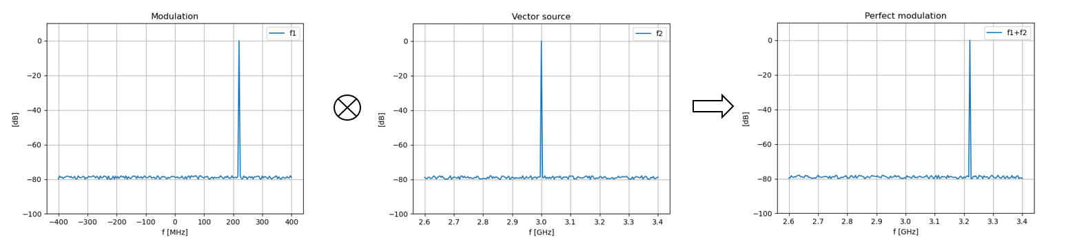
Ideal IQ modulation
In practice the signals and electrical components are not perfect. Small differences between amplifiers, filters and path length result in small errors in the IQ output.
The I and Q output of the AWG can have a voltage offset, a (frequency dependent) gain difference and a (frequency dependent) phase difference. The output signal after modulation will contain the carrier frequency and the mirror side-band.
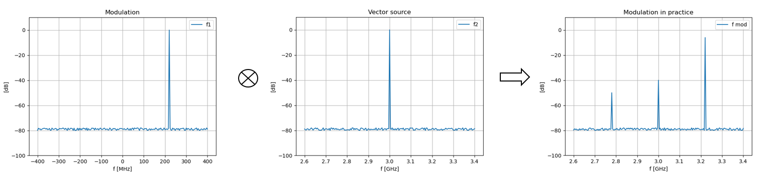
IQ modulation in practice with remainder of the carrier frequency and a mirrored side-band.
Offset error
A voltage offset in the AWG output results in the output of the carrier frequency.
\(y(t) = [a+cos(\omega_m t)] cos(\omega_c t) - [b + sin(\omega_m t)] sin(\omega_c t)]\)
\(y(t) = cos((\omega_c + \omega_m) t) + a \cdot cos(\omega_c t) - b \cdot sin(\omega_c t)\)
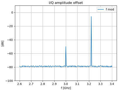
Remainder of carrier frequency due to offset error.
Gain error
A difference in gain between I and Q components add the mirrored side-band frequency, \(f_c - f_m\), to the output.
\(y(t) = (1 + a) cos(\omega_m t) cos(\omega_c t) - sin(\omega_m t) sin(\omega_c t)\)
\(y(t) = (1+\frac{a}{2}) cos((\omega_c + \omega_m) t) + \frac{a}{2} cos((\omega_c - \omega_m) t)\)
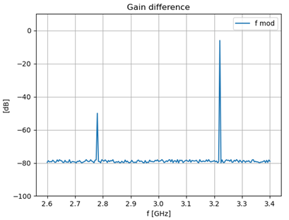
Mirrored side-band due to gain error.
Phase error
When the phase difference between the I and Q components is not exactly 90 degrees then the mirrored side-band frequency is output as well. The resulting output is similar to the output with a gain error.
\(y(t) = cos(\omega_m t + \frac{a}{2}) cos(\omega_c t) - sin(\omega_m t - \frac{a}{2}) sin(\omega_c t)\)
\(y(t) = cos(\frac{a}{2}) cos((\omega_c + \omega_m) t) - sin(\frac{a}{2}) sin((\omega_c - \omega_m) t)\)
IQ corrections in pulse_lib
A vector signal generator will have options to correct the offset, phase and gain error of the IQ input, but only with a frequency independent correction. Pulse_lib can also correct for these errors, where gain and phase corrections are frequency dependent.
- Example:
Add offset correction to I and Q components.
pl.add_channel_offset('I1', 10)
pl.add_channel_offset('Q1', -5)
Add gain and phase offset to qubit channels.
IQ_pair_1.add_virtual_IQ_channel("q2", 2.421e9,
                                 correction_gain=(1.0, 0.9))
IQ_pair_1.add_virtual_IQ_channel("q3", 2.473e9,
                                 correction_gain=(0.98, 1.0),
                                 correction_phase=0.3)