Bias-T
The plunger and barrier gates of quantum dots have a DC voltage offset to maintain the desired operational regime. The gates are pulsed for the initialization, manipulation and readout of the qubit state. The DC voltage source and the AWG-generated pulses are combined by means of a bias-T.
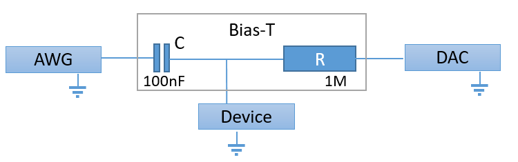
Bias-T connecting the high frequency AWG and the low frequency DAC to the device.
The bias-T is a T-like component which acts as a high-pass filter for the AWG pulses and as a low-pass filter for the DC voltage. It consists of a resistor and a capacitor with values in the order of 1 MOhm and 100 nF giving an RC-time in the order of 0.1 s. The a cut-off frequency \(f_c = 1/2\pi R C\) is in the order of a few Hz.
he high-pass filter on the AWG signal results in amplitude decays for long pulses and accumulation of an offset when the average voltage of a sequence is not zero. This offset will grow with every repetition of the sequence until the offset is has the negative voltage of the average of the sequence.
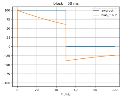
Decay of the amplitude of a long block pulse due to the bias-T high pass filtering with RC-time = 0.1 s.
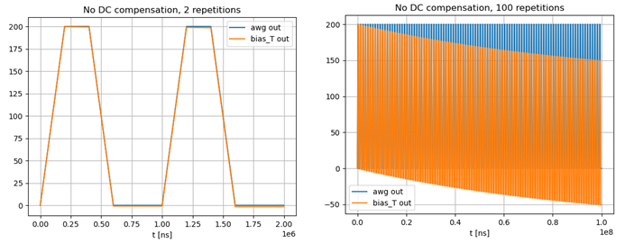
The deviation after 2 pulses of ~0.5 ms is only 1.6 mV. After 100 repetitions the deviation is > 50 mV.
DC-compensation
The average voltage of a sequence should be 0.0 V to avoid a growing voltage offset due to the bias-T high pass filtering. Pulse_lib will automatically add a DC-compensation pulse when the average of a sequence is not zero. This DC-compensation is enabled for all channels where the channel compensation limits are set.
Note: Contrary to all other settings, the compensation limits are set in AWG voltage, not the device voltage.
- Example:
Enable DC-compensation for channels P1 and P2 with limits of -200 and +500 mV.
pl.add_channel_compensation_limit('P1', (-200, 500))
pl.add_channel_compensation_limit('P2', (-200, 500))
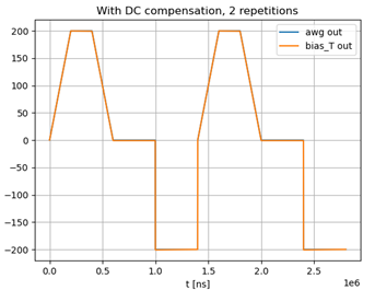
DC compensation with automatically added pulses of -200 mV at the end of the sequence.
Bias-T compensation
Sequences with long pulses or long sequences with the average voltage not equal to zero will be distorted by the bias-T when the duration exceeds a few percent of the RC-time. Pulse_lib will compensate for the bias-T high-pass filtering when the bias-T time compensation is configured. This bias-T correction will increase the sequence compilation time with a small percentage.
The bias-T compensation can correct pulses with a duration in the order of the RC-time. Pulses that are longer than a few times the RC-time will eventually hit the limits of the AWG output range, because the bias-T compensation increases the amplitude of the signal. A good correction of long pulses is only possible when the configured RC-time is accurate enough. An error of 2% in the configured RC-time gives an error of 10% in the amplitude at the end of a pulse with a duration of 5 times the RC-time.
Note: The time of the bias-T is specified in seconds!
- Example:
Enable bias-T compensation for channels P1 and P2.
pulse.add_channel_bias_T_compensation('P1', 0.102)
pulse.add_channel_bias_T_compensation('P2', 0.106)
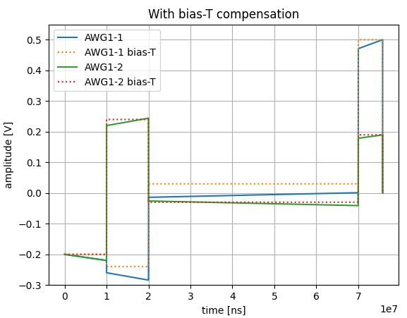
Bias-T compensated pulses. The dashed lines show the signal after bias-T with the desired rectangular pulses.